Mechanical drive systems employ splines. They can be found in the spinning machinery we observe daily. A spline is used in almost every device that transmits circular motion from an input to an output. Splines use a mechanical connection, or splined shaft, to convey the rotating motion of an input to an output. A splined shaft has teeth that are evenly placed around the circumference and are normally parallel to the shaft’s axis of rotation. Straight-sided teeth, as well as angle forms (serrations) and involute forms, are available. The outwardly splined shaft is mated to an internal spline with slots, or gaps, produced in the opposite direction as the teeth on the shaft.
There are several advantages to utilizing a splined shaft instead of a keyed shaft: The spline connection distributes the weight evenly along the sides of the teeth. In comparison to a keyway drive, this shared load delivers a longer fatigue life. Stronger drives, the ability to slide, the transmission of rotational concentricity, the capacity for misalignment, and, in the case of helical spline drives, the simultaneous transfer of axial and rotational motion are all possible with different types of spline tooth shapes.
Here are some of the techniques where the involute splines hob is used:
- Milling: Serrations, parallel or involute splines, and serrations can all be machined. The intervals between the teeth are machined with a double-angle milling cutter intended to provide the space of a serration or parallel key spline shaft. Involute splines are machined with a milling cutter that has the reverse shape of the involute for that specific diametral pitch, pressure angle, and the number of teeth. The index between teeth is provided by an index, dividing head, or CNC rotary table.
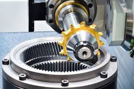
- Hobbing: The hobbing process may be used to make any form of an external spline. The cutting tool is a cylindrical hob with the mating rack shape of the spline to be created. The hob then “rolls” with the spline, much like gear would with a rack, traversing the work along the axis of rotation. The hob’s cutting teeth scrape material out of the gaps between the spline teeth.
- Shaping: Internal and external splines may both be created using this approach. A shaper cutter is a disc with a cutting edge on one face and a certain number of teeth, diametral pitch, and pressure angle. The differential gear train or programmed ratio for the shaping machine is determined by the ratio of the number of teeth in the cutter to the number of teeth in the work. The precise rotational ratio between the cutter and the job is determined by this.
- Broaching: This procedure is utilised to create all forms of female splines. The broach tool is tailored to the internal spline for which it was created. The tool has the right amount of teeth and the right shape for the female spline it’s supposed to make. It is a cutting tool with many cutting edges positioned along the length of the instrument. The broach’s beginning end has a smooth diameter that fits into the work’s smoothbore. Cutting edges at predefined equal axial distances are located as you progress from this end to the opposite end of the instrument.
The last spline of each cutting edge has a steadily increasing shape. This allows each cutting edge to have a precise chip load as it is drawn or pushed through the machine.
These are some of the methods where hob cutter manufacturers are used.